|
|
[1]
[2]
[3]
[4]
[5]
[6]
[7]
[8]
[9]
[10]
[11]
[12]
[13]
[14]
[15]
[16]
[17]
[18]
[19]
[20]
[21]
[22]
[23]
[24]
[25]
[26]
[27]
[28]
[29]
[30]
[31]
[32]
[33]
[34]
|
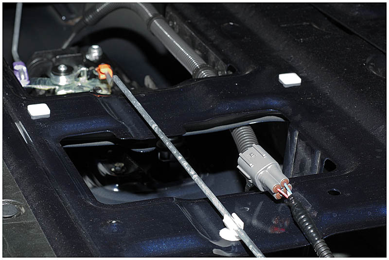
When I ordered the truck, I had requested to the dealer that they install Toyota's back up camera - camera module only. This is a neat little package with a fisheye lens camera built into the tailgate latch:
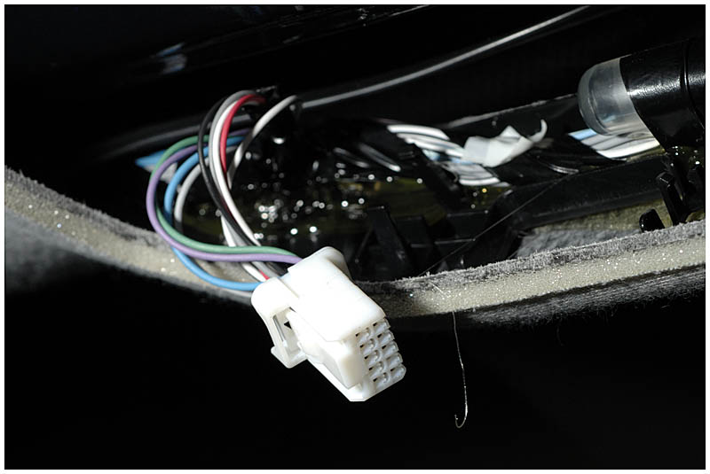
So now came up the the question of the connections to it. I knew it was in the headliner but I didn't see anything that looked like it would be connected to a camera. A quick drive over to the dealership proved that it was indeed this little connecter towards the front:
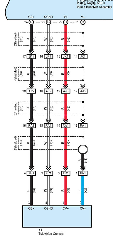
...but again, this is not what you would expect video on. There was four wires taped together as per the schematic:
To be safe, I pulled the tailgate apart and checked for continuity on the wires:
Sure enough, these are the right wires. So I spliced a sheilded RCA cable to the video feed (red V+, grey V-) and a red/black cable for the camera power (black B+, white GND):
A Tundra Solutions forum member (1tundradude) discovered in a Toyota document that the supply voltage for the back-up camera is supposed to be between 5 and 7 volts. Normally, this regulated voltage would be supplied by Toyota's monitor but since I am using the Alpine display, I have to provide it myself.
Luckily, this is an easy fix - all that is required is a Voltage Regulator. I had on hand an NTE956 which is a generic version of an LM317. This is an adjustable voltage regulator whose output is set with a simple voltage divider:
A couple quick calculations finds my resistor values (R1 = 100ohms and R2 = 420ohms) and I can solder it together. Of course it is rare to find the exact values for resistors so I had to put a 220 and a 200 in series.
Regardless of my input voltage, the output remains steady at 6.76v:
A bit of heat shrink to protect the connections:
And it is soldered in line:
All these cables were fished down the A-pillar and over to the center console.
| ||||||||||||||||


